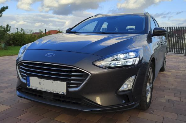
This article summarises my experience in fitting in static full LED headlamps into my Ford Focus MK4 as a replacement of halogen headlamps. These headlamps:
There are five types of headlamps for Focus MK4:
- full halogen with LED DRL
- full static LEDs - with auto-levelling and HCM module, in production till fall 2019
- full static LEDs - without auto-levelling, with manual levelling, no HCM, in production since fall 2019
- adaptive full LEDs, require HCM and levelling sensors
- half LEDs (LED: low beam, DRL, bulbs: high beam, turn), in production since fall 2019, replaced full halogen ones
I have mounted full static LEDs - without auto-levelling. This does not require suspension sensors and no HCM module (Headlamp Control Module). Wiring is much simpler. Also, there is no need to replace the lamp control panel, auto leveling headlamps cars have no the leveling knob. We need the manual leveling knob!
- Theory
These headlamps use manual leveling, the same way halogen does. They have no auto-leveling motors at all. That’s the only difference between the auto-leveled version. Others are the same: headlamps need High Beam (HB) line to be used as power supply instead of HB turn on signal. The HB are controlled via LIN bus, Low Beam (LB) are controlled via LB line but there is no power going through this line, it is a “voltage” signal. Turn and daylight (DRL) works the same as in halogen headlamps.
One more difference for turn lights is the outage detection. In halogens, detection is based on current measure. In LEDs, there is a special signal going out of headlamps. Since there is a way to turn off outage detection, I gave up connecting these signals, but I have laid cables, just in case.
The challenge was to figure out where the hell LIN bus signal is connected to?
- Wiring
DISCONNECT THE BATTERY BEFORE ANY WIRING JOB ESPECIALLY DISCONNECTING BCM CONNECTORS!
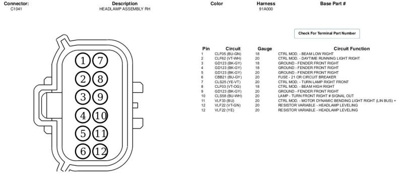
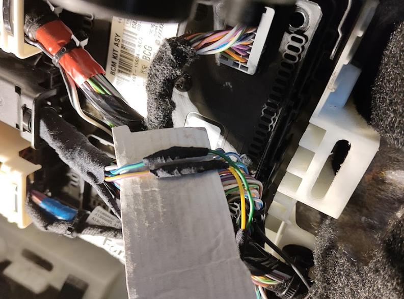
There are some “players”: headlamp connectors (C1041, C1021), Body Control Module (BCM) located under the glove compartment and its C2280E connector (middle one).
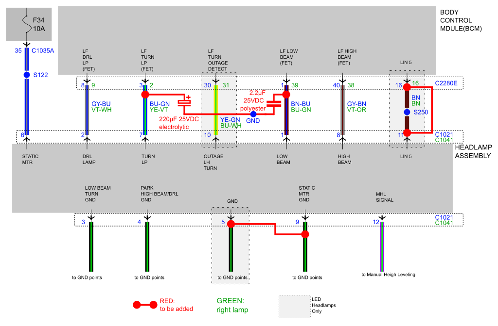
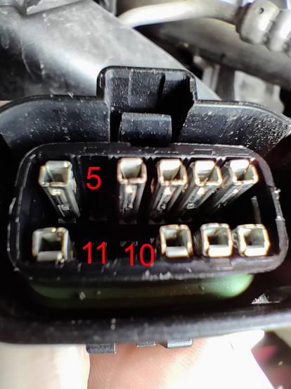
I made the following wiring (marked in RED on the diagram above):
- LIN bus: pin#11 of each lamp to pin#16 of C2280E of BCM.
- pin#5 to pin#9 of headlamps, not sure if needed, better to do it.
- pin#1 and pin#5 (ground) to a 2.2uF capacitor, explained later
- pin#7 and pin#5 (ground) to a 220uF capacitor (to be done in the cabin), explained later
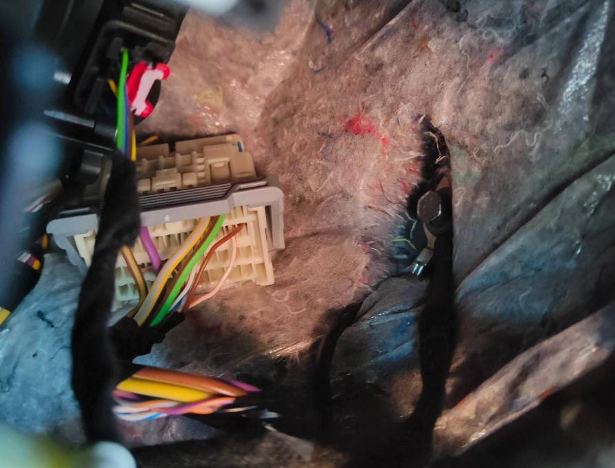
The best way to do it, is to buy a second hand MOLEX plug from another Ford as pins “donor”. Quite popular type of connector. I have found one from Mustang, it’s bigger so more pins. Pins are with a tail of a cable, I call it a “pigtail”.
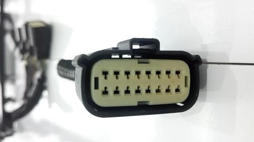
And, it is good to exercise the opening process of our precious connectors in the car.
Half job done:
Ready :
For the capacitor, I have put a tail terminated with a socket since I was not sure about capacitance to use. Now it is known that needed, 2.2uF is enough.
One must have some moderate soldering and wiring skills. All shall be protected with heat shrink tubing, as you can see, I use glued ones. And protective automotive tape.
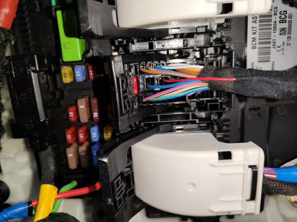
Note about fitting-in the pigtails. Firstly, remove the cover on the cable side, break away protectors from the pin we are going to add, then close it back. Then, lift up the white cover using a small screwdriver, gently. Push new pigtails inside and close it.
There are 3 pins missing: LIN bus, turn outage and a ground:
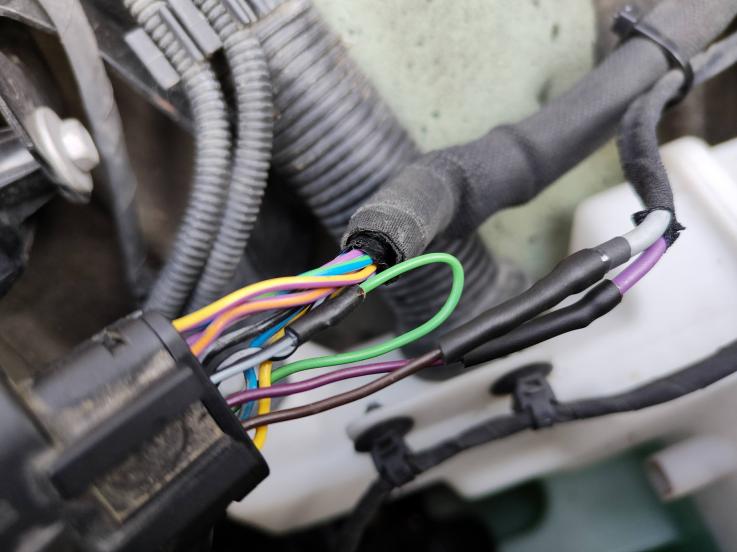
The LIN bus cables were shielded for headlamps with auto-leveling. For these without, the wiring diagram does not show shields. Nevertheless, I have laid shielded cables. It is better of course but there is an issue to find a ground point close to BCM. There is one opposite to the glove compartment, but it is not easy to find and connect. I did it anyway:
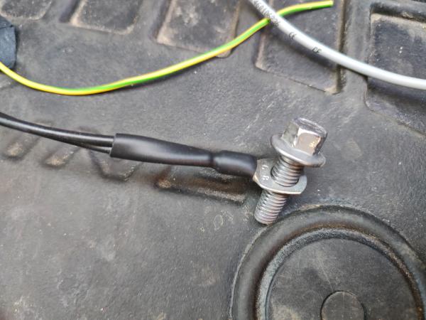
Shielded cable shall be connected to the ground only on one side. The alternative is to connect on the headlamp side. Shall not be differens.
BCM: pin#16 of the connector C2280E.
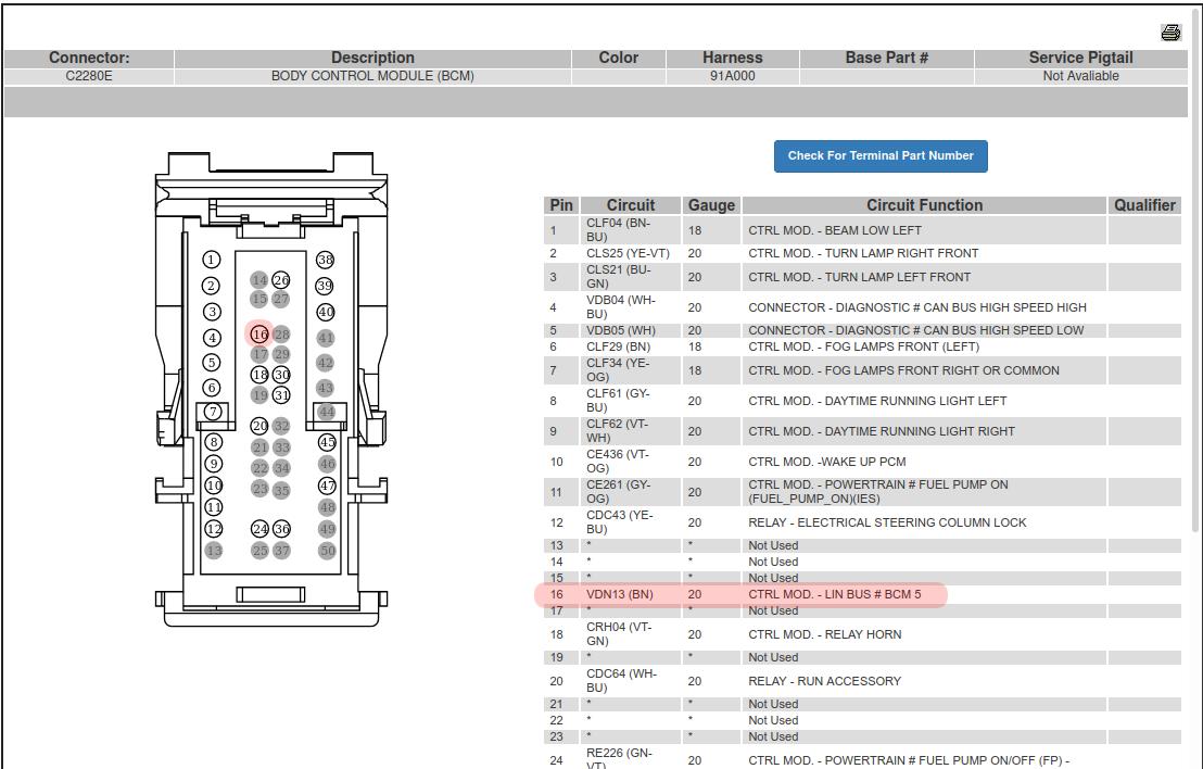
The LIN bus #5, that is pin#16 of C2280E need to have a pin added. The pin is small, similar to that used in the computer industry but has a bit different shape which locks it well in the connector body. It is also good to look for secondhand connectors or some dedicated pins, there are on the market.
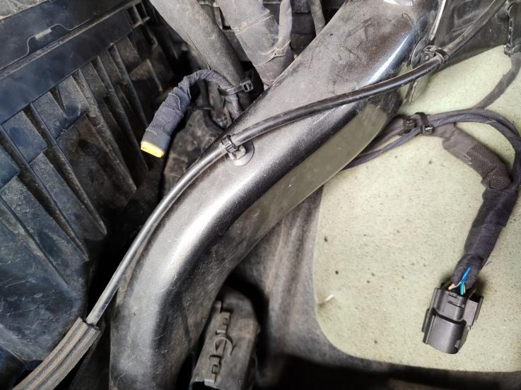
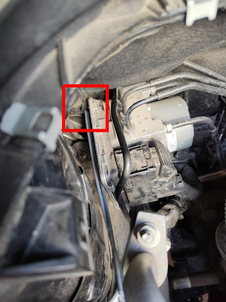
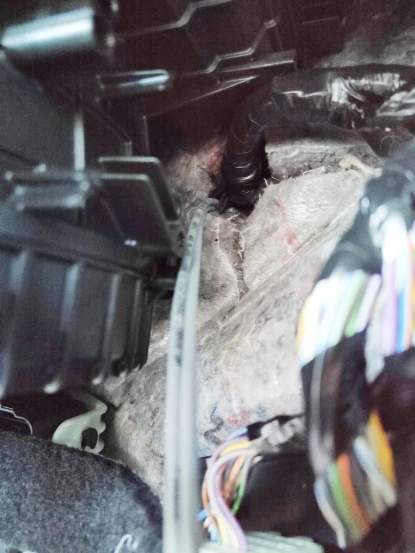
Cables must go from the engine part to the cabin. It is not an easy task. I have used a culvert on the passenger side. Depending on a LHD or RHD car it might be different. The right one was easier anyway.
There is a small “nipple” left free (at least in my car). You can make a hole in it from inside with a stiff sharp rod. Then try to make the hole a bit bigger with a bigger and scratching rode. I have put a heat shrinking tube on the engine side - half shrinked. When pulled from the cabin side, the tube covered the nipple. Any other way to pass cables is good. The cable for the left headlamp is tricky to lay, actually there is a need to unmount the battery (which needs to unmount the air filter intake).
- Programming
There is an official set of options in the Forscan software. I don’t know UCDS or others. The bits I have changed were found using a special statistical analysis of about 20 cars. I have a tool which compares the number of AsBuilt data files, finding unchanged bits in two groups, then comparing only these bits between the groups. The idea is to make two groups of AsBuilt data, one without a feature, second with the feature. This way, we filter out many unrelated to the feature bits.
In BdyCM (aka BCM) module:
- Programming
There is an official set of options in the Forscan software. I don’t know UCDS or others. The bits I have changed were found using a special statistical analysis of about 20 cars. I have a tool which compares the number of AsBuilt data files, finding unchanged bits in two groups, then comparing only these bits between the groups. The idea is to make two groups of AsBuilt data, one without a feature, second with the feature. This way, we filter out many unrelated to the feature bits.
All changes are also here for easy programming: ForMOD AsBuilt Calculator, led headlamps
- HB line as power
Use explicit Forscan configuration, it has to be done for left and right. Easy to find “Left/Right Front High Beam Usage”
- Disable “Front Bulb Turn Outage”, enable “Front Bulb LED Outage” if connected the cables
- LIN#5 bus activation
Bits to set
word: block 1 block 2 block 3
byte: msb lsb msb lsb msb lsb
nibble: ----____ ----____ ----____ ----____ ----____ ----____
bit: FEDCBA98 76543210 FEDCBA98 76543210 FEDCBA98 76543210
726-12-01 ........ ........ .. .... ..11.... ........ ........
726-14-08 .1...... ........ ........ ........ ........ ........
726-17-01 ........ 1....... ........ ........ ........ ........
Or bytes to change:
was: 726-12-01: xxxx xx0x xx
changed: 726-12-01: xxxx xx3x xx
was: 726-14-08: 8xxx xxxx xx
changed: 726-14-08: Cxxx xxxx xx
was: 726-17-01: xx0x xxxx xx
changed: 726-17-01: xx8x xxxx xx
was: 726-21-03: 4Axx xxxx xx
changed: 726-21-03: 02xx xxxx xx
After that, once I had headlamps connected I did the Forscan procedure for BCM “testing module connection”. Not sure if it is necessary, It was for the reverse camera so I did.
- Other bits I have found, but I’m not sure if they are needed or not. I have set them anyway:
word: block 1 block 2 block 3
byte: msb lsb msb lsb msb lsb
nibble: ----____ ----____ ----____ ----____ ----____ ----____
bit: FEDCBA98 76543210 FEDCBA98 76543210 FEDCBA98 76543210
726-27-02 ..11.... ... . .. ... . .. ........ ........ ........
Or bytes to change:
was: 726-27-02: 0xxx xxxx xx
changed: 726-27-02: 3xxx xxxx xx
- IPMA
There is a setting in the camera module, easy to find in Forscan. Probably makes a difference for recognition algorithms. Anyway, change headlamps in the IPMA module to LED.
- Low Beam/Turn Flickering
One unresolved issue is flickering of the LB when the engine is started. This comes from voltage stabilization for halogen bulbs. It is 100Hz PWM. When driven directly to the LB LED, makes LB flickers. I have found the following bits, which are set to “0” for any LED headlamps. Looked perfectly (something turned off) but had no result. It might be that my BCM has the wrong hardware or software.
word: block 1 block 2 block 3
byte: msb lsb msb lsb msb lsb
nibble: ----____ ----____ ----____ ----____ ----____ ----____
bit: FEDCBA98 76543210 FEDCBA98 76543210 FEDCBA98 76543210
726-21-03 .0..0... ........ ....... .... . . ........ ........
Or bytes to change:
was: 726-21-03: 4Axx xxxx xx
changed: 726-21-03: 02xx xxxx xx
There is also “Frequency Type Selection” in the Forscan BCM configuration, most LED cars have it set to “type 3”, mine was “type 2”. Setting any value does not make any difference in my BCM.. This setting solved the flickering problem on some Ford Track cars.
Since the LB line is no longer a high current line, it is only a turn on signal, a small capacitor can filter PWM to the level where headlamps stop flickering. I tested 1uF and it works, so 2.2uF is a safe capacitance. Use some good quality capacitor, poliester type with a high temperature range. Do not use electrolytic capacitors if mounted under the bonet!
Same applies to the TURN signal. The PWM switching makes turn lamps flicker. To mitigate this, 220uF capactor is needed. This rather will be an electrolytic capacitor and it is better to mount in the cabin. Capacitor shall be high quality, 25VDC minimum. It is not complicated sine cables are easy to access. These are yellow-violett and blue-green cables. WARNING: There are two green-blue cables in this connector, see the diagram, the other one is for RF low-beam!
- Headlamps to Buy
Headlamps I have mounted:
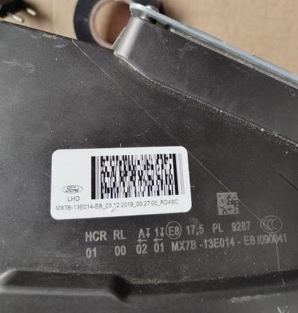
MX7B-13E015-EB
MX7B-13E014-EB
These are LHD, not sure about RHD. Also, these are "black" that is for STline. Ones marked JX7B are old ones requiring HCM and suspension sensors - a lot of work.
You can search for ones with broken away mounting "wings", they are cheaper. Ford original repair kits are great. Don't go for repaired units, repairing never works. Repair kits: JX7B-13A004-AA JX7B-13A005-AA
I have also found fake ones, they had no laser prints one the cover looked suspicious. Genui ones look like that:
- Mounting Headlamps
The LED headlamps are somehow bigger than halogens. It is very difficult to mount them, so do not be surprised. I made loose an upper part of the body, which allows to pull it 5-10mm, it helps. Be careful about this metal side, it is sharp and can scratch the lamp.
- Auto High Beam (AHB)
If you are lucky and have a proper version of IPMA (camera module: -Bx or -Cx symbol suffix) you can activate Automatic High Beam feature:
IPC:
was: 720-01-01: xxxA xxxx x0
changed: 720-01-01: xxxE xxxx x2
was: 720-10-01: xxxx xxx0 xx
changed: 720-10-01: xxxx xxx1 xx
IPMA:
was: 706-01-01: xxxx x5xx xx
changed: 706-01-01: xxxx x9xx xx
BdyCM:
was: 726-11-04: xxxx xx4x xx
changed: 726-11-04: xxxx xxCx xx
SSCM:
was: 724-02-01: xxxx 68xx xx
changed: 724-02-01: xxxx 70xx xx
I have based on this spreadsheet(big thanks for neutron2k!) and Forscan settings for AHB. I have also verified this settings comparing many different cars.